PuTTY ssh client: eliminate modal Fatal Error pop-up

As a Linux sysadmin, I spend hours per day using the PuTTY SSH terminal emulator. It is a small, fast and lightweight application that works well and requires little attention.

PuTTY only has one annoyance that I’ve noticed: if a connection fails or drops, it puts up a modal “PuTTY Fatal Error” dialog. If I have many connections up and then hibernate, lose connectivity, or take the laptop to a new location, they all break. I would like to just right-click PuTTY in the Taskbar and choose “Close all windows” but that does not work because of the modal dialogs. I have to click on each session, dismiss the dialog, and close the window.

Since PuTTY is a small and lightweight open-source application, this nuisance should be easily fixable. The error should display in the PuTTY window itself rather than in a pop-up dialog.

My first problem was to get a build environment up. I brought up a temporary Windows Server 2019 Base at AWS and downloaded: https://visualstudio.microsoft.com/downloads/#build-tools-for-visual-studio-2019 onto it. I only installed the C++ build tools. Use the \\tsclient\c path to access local files from the VM, assuming you enabled drive sharing under Remote Desktop Connection/Local Resources.

PuTTY source is here: https://www.chiark.greenend.org.uk/~sgtatham/putty/latest.html under Windows source archive.

Using PuTTY 0.73 source, the code change required is in windows\window.c function win_seat_connection_fatal() around line 1196. Here is the change:

/*
 * Print a message box and close the connection.
 */
static void win_seat_connection_fatal(Seat *seat, const char *msg)
{
 char *title = dupprintf("%s Fatal Error", appname);
 win_seat_output(seat,0,"\r\n------------------------------------------------------------------------\r\n",76);
 win_seat_output(seat,0,title,strlen(title));
 win_seat_output(seat,0,": ",2);
 win_seat_output(seat,0,msg,strlen(msg));
 win_seat_output(seat,0,"\r\n",2);
 // MessageBox(hwnd, msg, title, MB_ICONERROR | MB_OK);
 sfree(title);

if (conf_get_int(conf, CONF_close_on_exit) == FORCE_ON)
 PostQuitMessage(1);
 else {
 queue_toplevel_callback(close_session, NULL);
 }
}

The MessageBox call, which I commented out, generates the modal pop-up. I replaced it with calls to win_seat_output to print to the terminal window instead. That one function is all that has to be changed.

Now to compile it. After installing VC Build Tools and copying the modified PuTTY source under Downloads, I did:

cd c:\Users\Administrator\Downloads\putty\windows
"c:\Program Files (x86)\Microsoft Visual Studio\2019\BuildTools\VC\Auxiliary\Build\vcvarsall.bat" x86_amd64
nmake -f Makefile.vc
copy putty.exe \\tsclient\c\bin\

The new PuTTY is now in my local C:\bin directory and is ready to use. Here’s what a disconnect looks like now:

Data extraction from a Foxwell NT520 Pro car diagnostic scanner

The Foxwell NT520 Pro, and a few other models from Foxwell Technology, are car diagnostic scanners that can access a lot of manufacturer-specific data.

Most cheap scanners can only access the OBD II engine data, which is required by law to have a standard format. The Foxwell can access that, but can also get at manufacturer-specific data for things like the transmission, brakes, gauges, power windows, and air conditioning.

The unit comes with OBD II and one manufacturer-specific module. You can buy it with the module already loaded, or you can download the module yourself using a proprietary PC application. To get more than one manufacturer-specific module, you have to pay $60 per additional module.

In my case I have the Honda module for a 2007 Acura TL. The scanner will show engine data, transmission data, brake pressure, and even keys registered to the car. You can turn on and test individual dash lights, make the speedometer or tachometer show any value, and probably mess up your car with some of the configuration options.

In addition to real time display and subsystem tests, it can continuously log a series of parameters. Choose Live Data and Save. You can select all parameters for the engine, all parameters for the transmission, or a subset of the parameters. The fewer you log, the faster it samples.

There is a playback option that is supposed to display the stored data. Playback doesn’t work properly. It will display some but not all OBD parameters, and fails entirely for the Honda module.

The Foxwell uses a Micro SD card, so I pulled the card, plugged it into the PC, and went looking for the files. Turns out they are in a proprietary format, and I could not find a converter online, so I wrote my own.

The file extension is .cbf, and the format is basically ASCII strings with null byte terminations and a few binary integers that have to be parsed to make sense of things. The converter will generate either HTML or CSV from the CBF files.

The Foxwell does not log time of day, so it is difficult to match performance data to your location while driving. If you want to mark a point in the engine log, hold down one of the cruise control buttons for a few seconds. Even though you are not using the cruise control, the corresponding “Cruise Sw” column in the engine data will toggle to On.  If you are logging automatic transmission data, the paddle shift buttons will be logged, even though they have no effect with the shift lever in Drive.

You can use the converter online or download the Python code. I have only tested with the OBD and Honda modules. If you encounter any CBF files my converter won’t parse, please send them to me so I can fix it.

Sample files:

Engine CBF Table
Transmission CBF Table
Brakes CBF Table
OBD II CBF Table

Why not Bluetooth for TV remotes? [Caavo]

There is a review here:
https://www.theverge.com/2018/2/14/17011010/caavo-remotes-review
of a new universal remote control called Caavo. This system goes to extremes to control video devices: it has a smart HDMI switch that connects to your TV and all types of streaming and media playing devices. The switch actually decodes the video and “looks at the screen” to figure out what state your Apple TV or Xbox One is in, and then emits infrared signals (as well as Ethernet and HDMI-CEC control signals) to control the devices. Their goal seems to be providing a single interface to select content from any source.

This has to be a fairly powerful computer to process and interpret video. The manufacturer must have a huge lab with One Each Of Everything and a team of software developers watching for firmware upgrades and pushing out new control profiles to the devices. Caavo is making a heroic effort to do something that the manufacturers have made hard: automatically control AV devices. Good for them but there ought to be a better way.

TV remote technology is stuck in the 1980s. There have been four generations of TV remotes. Gen 1 (1950s Space Command) had a light sensor at each corner of the screen. The remote control was a flashlight.

Gen 2 (1960s) was acoustic with a microphone in the TV, a tuned circuit for each function, and a set of mechanical chimes in the remote. The tuner knob on the TV actually moved when you operated the remote. DING – kerchunk!

Gen 3 (1970s) was ultrasonic with a piezoelectric transmitter and a battery in the remote. The TV still had a set of tuned circuits. There was one of these in my house as a kid, and jingling a large handful of quarters would reliably turn on the TV. It also came on full volume by itself a few times.

Gen 4 (1980s) uses an infrared LED and sensor. The remote transmits a carrier at some frequency like 32KHz (blinking on and off rapidly) and then modulates the carrier at a few hundred bits per second. The receiver is an integrated circuit that is tuned to the 32KHz carrier and outputs the bitstream. This is reasonably noise-immune, because there are few mechanical effects that can produce a 32 KHz flicker rate. One of my projects uses these remote sensors, and they are quite sensitive. They don’t work in full sunlight.

We are still using Gen 4 remotes. They are one-way, so the remote has no way to know what state the controlled device is in. You have to aim the remote at the TV, and sometimes devices interfere with each other. Universal remotes require arcane setup codes, and none of them control all the functions of every device. A few manufacturers have used one-way radio frequency control, which avoids the aim problem but also prevents the use of universal remotes.

The mobile device industry, by contrast, has successfully herded all the cats so Bluetooth actually works, at least for common functions. You can generally pair any headset with any phone. As a sysadmin I carry a Bluetooth keyboard for my phone, and that will also pair with just about anything that needs a keyboard.

So why not use Bluetooth for AV remote controls? It has more than enough range, the transceivers are cheap and low power, and there is already a mechanism to negotiate which functions each device can perform. This would allow for two-way remote controls. A universal remote would pair with all your devices, like a headset pairs with your mobile phone, and would map all the buttons automatically.

However, you probably would not need a separate universal remote, because any tablet or smartphone could act as a soft remote, with properly labeled buttons and the ability to execute macros.

Caavo is doing this the hard way because they have to: there is no cooperation between the hardware manufacturers, and each streaming provider wants to own the customer. However, if the mobile phone industry and the car industry can collaborate on Bluetooth, why can’t the home entertainment people do the same? If they don’t, the computer industry will replace them with more friendly devices.

How to use satellite data communication (with code)

One of my current projects needs to send and receive data from remote locations, so I have been working with satellite communication. This post will explain the Iridium Short Burst Data system and provide a simple Perl driver you can customize for your own project. I am using a Raspberry Pi with Raspbian Linux for this project, but any Linux PC works.

The unit I’m using is the RockBLOCK+ available here:
http://www.rock7.com/products-rockblock-plus
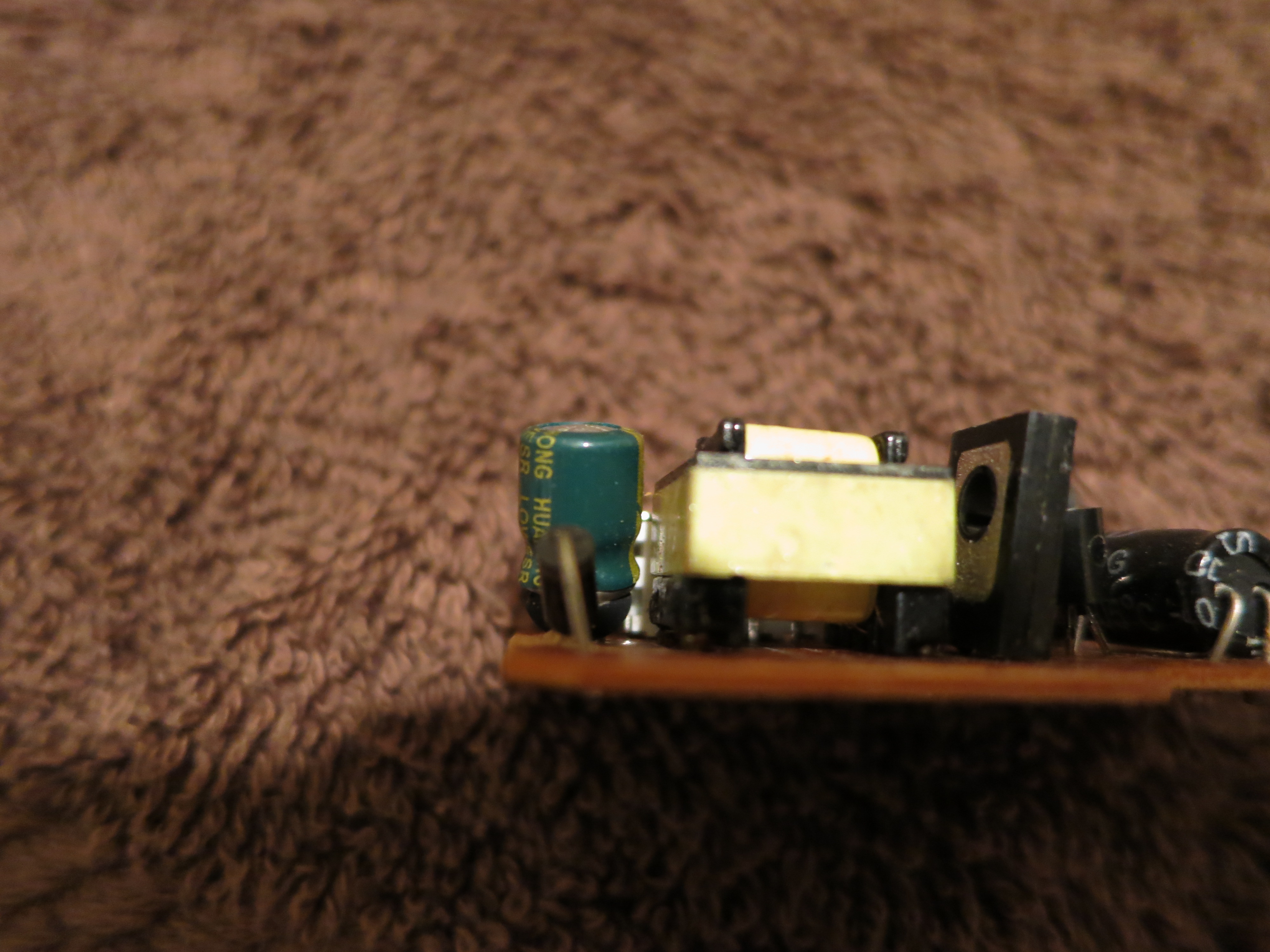
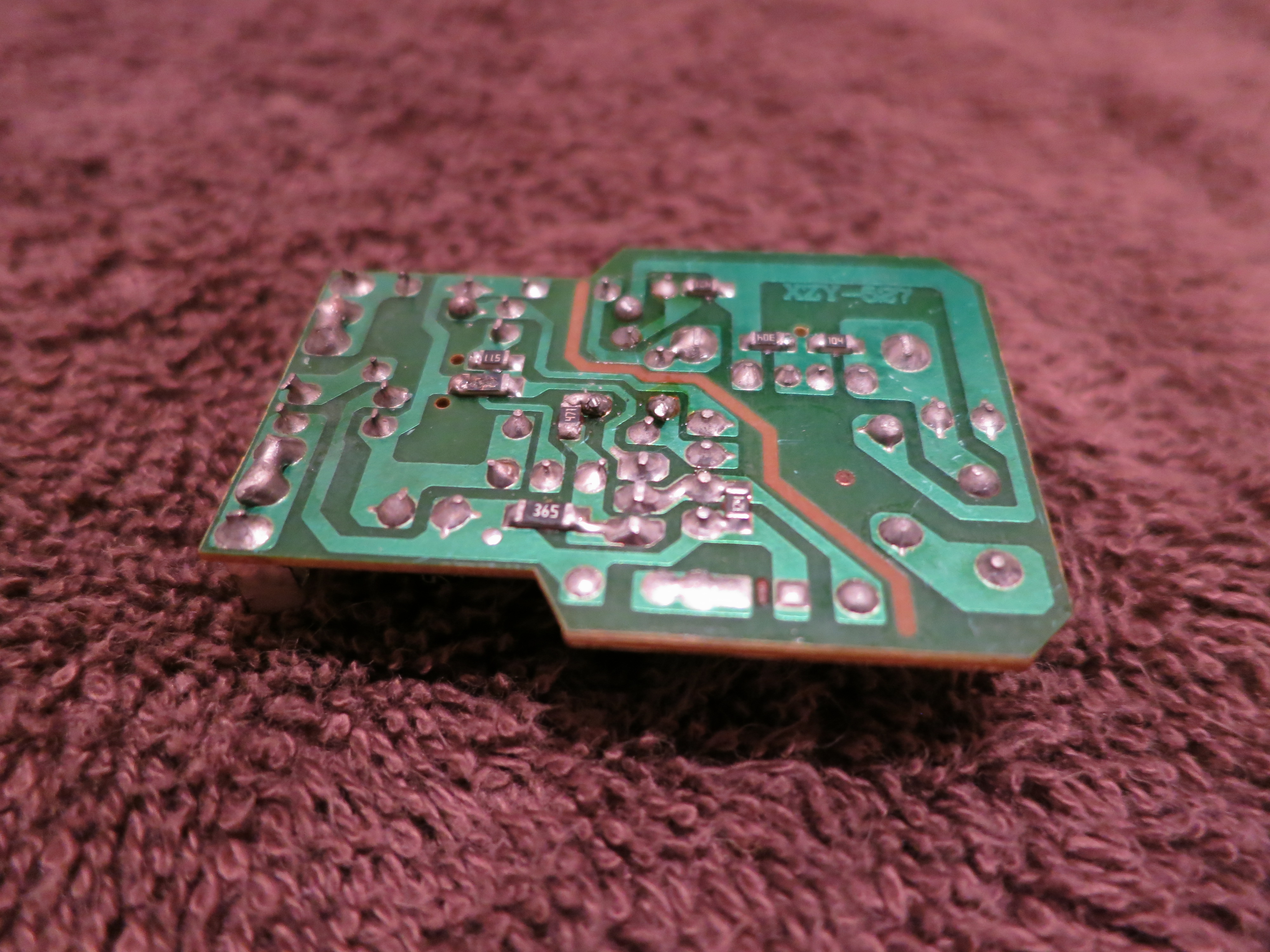
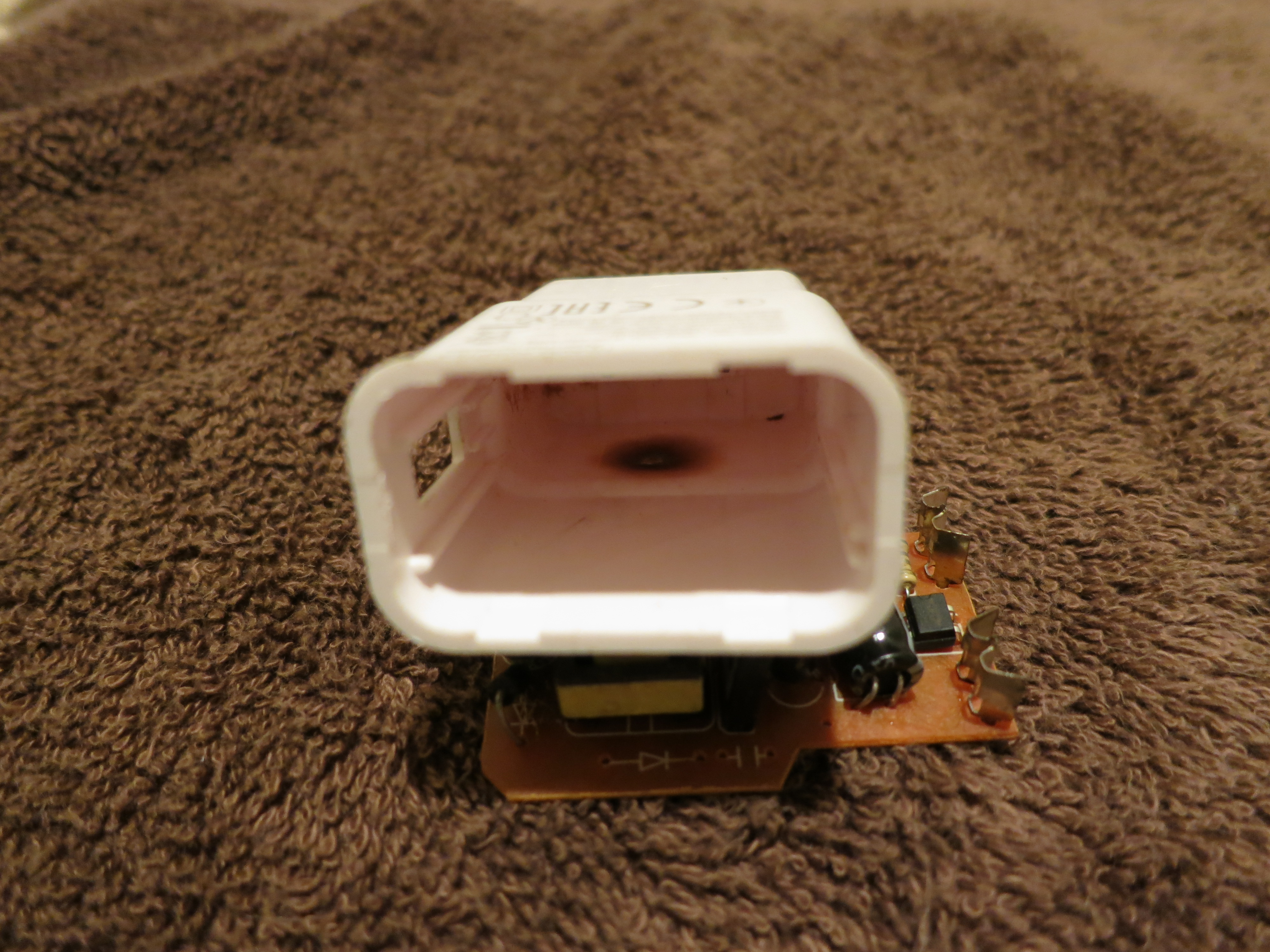
This device contains an Iridium 9602 Short Burst Data satellite modem, an antenna, a power regulator, and an RS-232 level converter in a 13cm weatherproof enclosure. Smaller units are available if you want to package them yourself.

Rock7.com is an intermediary between Iridium and your application. You can sign up with a credit card, much like a prepaid mobile phone. Other satellite services require contracts and fairly expensive up-front work, but Rock7 is very quick to set up. This device is the easiest way to send and receive data anywhere on the planet.

Iridium Short Burst Data is much like SMS text messaging, with one big conceptual difference: there is no recipient address in the mobile-originated message. Each message will be sent to the recipient addresses configured at the Rock7 website for your device. The messages are delivered to you by email or HTTPS POST.

The service is charged by the 50-byte unit, so a message up to 50 bytes, uplink or downlink, costs one credit. From 51 to 100 bytes costs two, up to a maximum message length of 340 bytes up and 270 bytes down.

The cost is GBP 10 per month per device, and GBP 0.11 to 0.04 per credit depending on the number of credits you buy. As a developer you have a strong incentive to keep these messages short. The protocol is binary, so you can use all 256 byte values. Binary or BCD rather than ASCII makes sense here.

You can send a message to the mobile unit either by typing it into the website, or by initiating an HTTPS POST to Rock7’s infrastructure. You can have multiple devices registered to one account sharing one set of delivery addresses and one pool of credits. Each unit is addressed by a 15-digit decimal IMEI number, and a password is required to send.

Iridium SBD devices like the RockBLOCK+ cannot communicate with each other. They can only send to and receive from a server on the Internet. If you want to communicate between mobile nodes, your server must relay messages. I have built simple text relay communication into my project, but this costs two credits per 50-byte mobile-to-mobile message.

The mobile unit must register with the satellite, which my code handles for you. When you send a mobile-terminated message, the satellite sends a one-way SBD RING broadcast. If your unit is turned on and pointed at the sky at that moment, it will receive the RING and my code will fetch the message and act on it.

The modem only has continuous coverage if you are outdoors with a clear view of the sky and the modem pointed straight up. Indoors with only a non-metallic roof overhead, the signal comes and goes as the satellites pass overhead. My code handles this and waits for a signal before attempting to communicate.

However, if the RING message is missed, the mobile will only discover it has a message waiting the next time it sends an outgoing message. You can also send the mobile another message to send another RING, but the satellite does not resend the RING on its own. This means you cannot count on the mobile being immediately reachable at all times. Your project should probably report in periodically, although this costs credits.

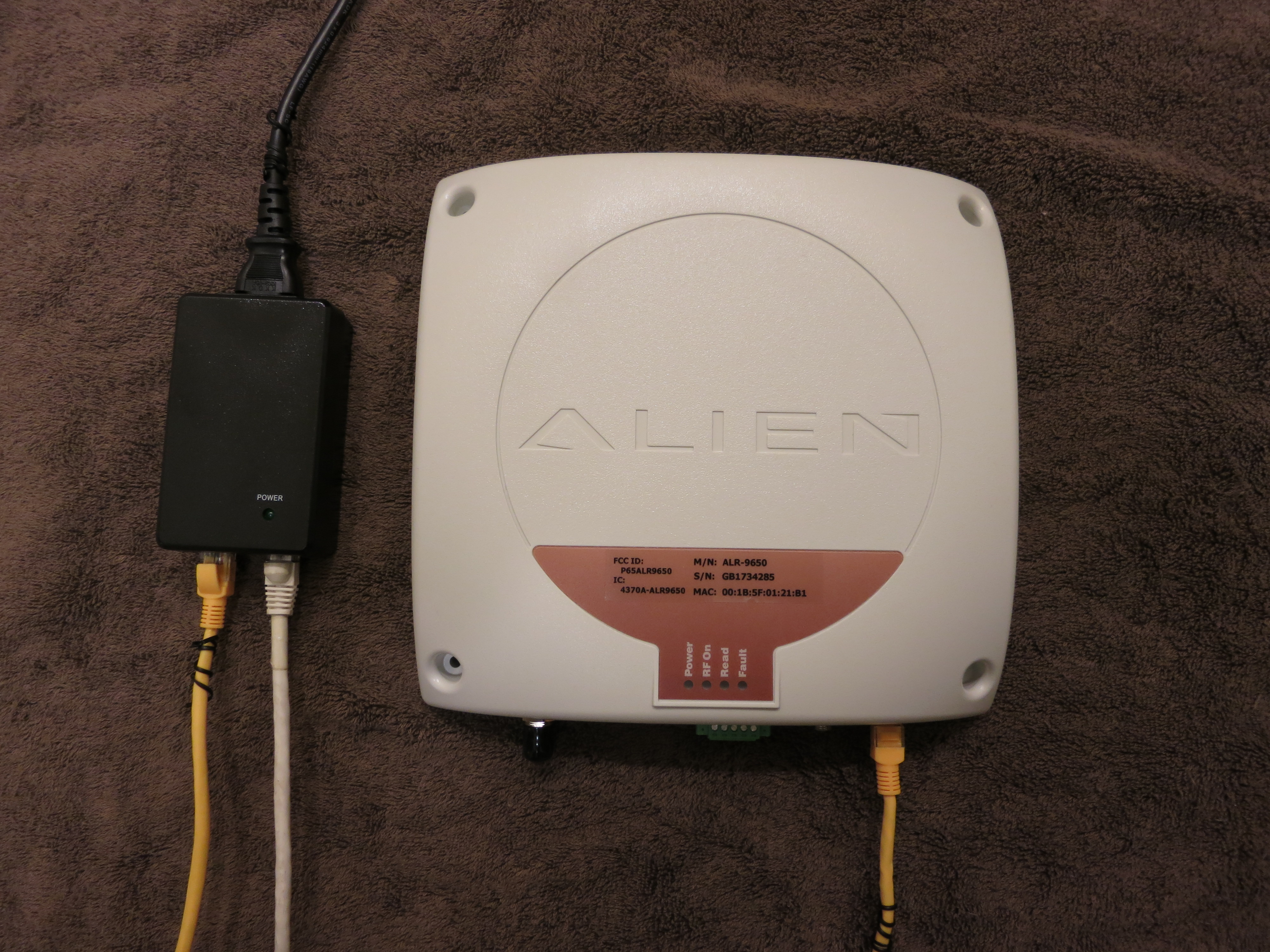
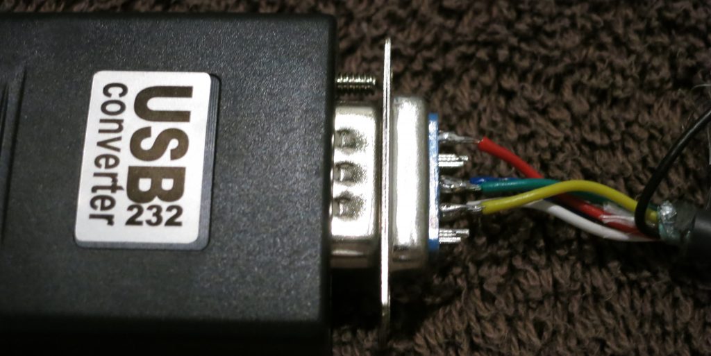
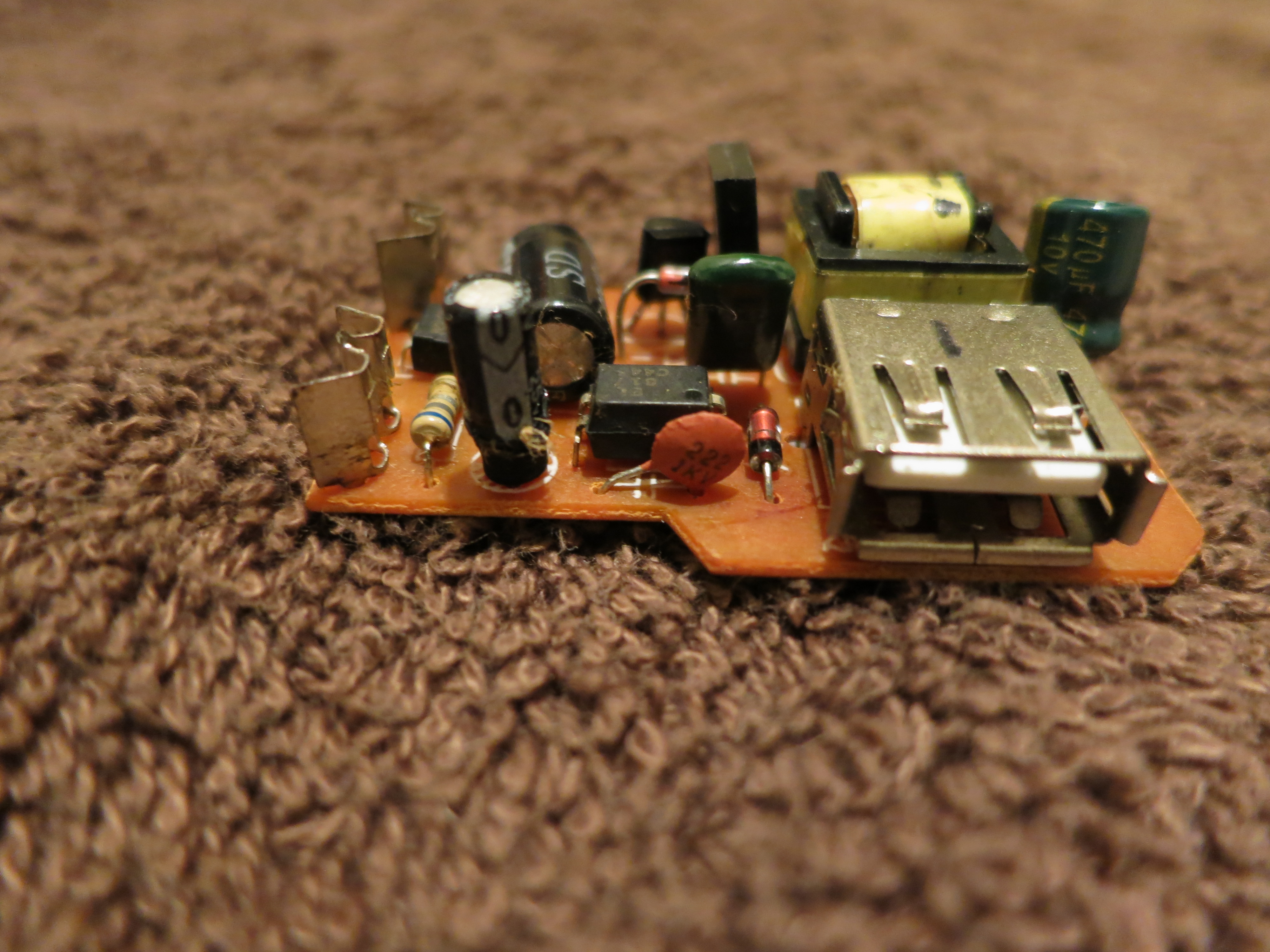
The modem comes with a long cable ending in bare wires. You will need to attach a DB9 female connector and a power source. If you have a power supply from a defunct laptop, those are usually 18 or 19 volts, and will work fine. Check voltage and polarity with a meter.

The unit requires 9-30 volts DC. Maximum current is 225 mA, because the device has a capacitor for momentary transmit power. Idle current (listening for incoming messages) is about 16 mA, and low power sleep is possible but not implemented in this project.
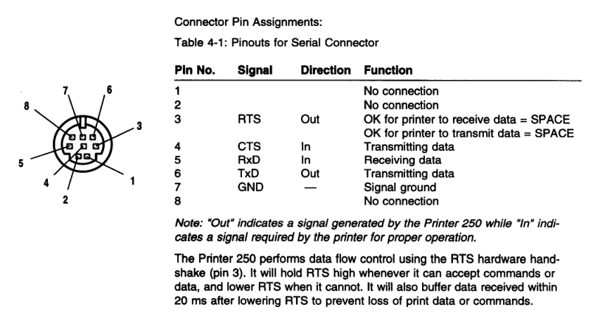
Wire as follows:

GREY – GROUND – DB9 pin 5 and power negative
BROWN – POWER – power positive
YELLOW – RX OUT – DB9 pin 2
BLUE – TX IN – DB9 pin 3

The rest of the wires can just be insulated. For the RockBLOCK+ you need a RS-232 type USB to serial adapter with a DB9 male connector. Some of the smaller non-packaged modems use TTL/CMOS levels, but the RB+ has a level converter.

You need the serial driver (sudo cpan install Device::SerialPort) installed. You should also install cu (sudo apt-get install cu).

To test the RockBLOCK+, power it up and run (assuming no other serial ports
are attached):

pi@raspberrypi:~ $ cu -l /dev/ttyUSB0 -s 19200
Connected.
AT
OK
~.

Disconnected.

If you get the OK, the RockBLOCK+ is connected properly. The satcom_p.pl program is a simple, single-file Perl driver that lets you send and receive text or binary data and define your own commands. There is a command already defined that runs shell command lines over the satellite.

Run it like this:

perl satcom_p.pl /dev/ttyUSB0

You will see a series of AT commands and responses, and the program will display the IMEI number. The program is now listening for commands over the satellite. Messages like +CIEV:0,4 indicate the signal strength (in this case 4 out of 5). At least 2 is required to send, in my experience.

Once you have a signal, go to the rockblock.rock7.com admin page, choose Send a Message, choose your Rockblock from the list, and in the Plain Text box type: sh uptime
and press Send.

Within a few seconds you should see SBDRING and then some activity on the Pi. The program waits for a signal of 2 or better, initiates a session with the satellite, fetches the incoming message from the downlink buffer, clears the downlink buffer, runs the command, puts the response in the uplink buffer, initiates another session with the satellite, and clears the uplink buffer. The modem does not automatically clear buffers, so my code checks this in a paranoid manner. If you fail to clear buffers, you will infinite loop and spend all your credits.

The shell command “uptime” will be run on the Pi, and the first 50 bytes of the output are sent back. You can click on Messages to see the reply. If you use sx (“shell expensive”) instead of sh it will return the first 340 bytes.

To add your own commands, find “sub process_message” in the program and add more patterns to the if-else structure. The incoming message will be in $msg (this can be binary) and you transmit using the satsend() function. More than one message can be queued for transmission. There is also a “sub periodic_poll” function where you can add timed operations such as reporting in at regular intervals.

It is normal to see occasional AT commands and signal strength updates. The driver polls the modem regularly even if nothing is happening. It is normal for send and receive attempts to fail, in which case the program waits 30 seconds before trying again.

My driver has a few file-based functions. If you touch the file nosend.flag, outgoing messages will not be sent to the satellite, but only displayed on the screen. You can fake an incoming satellite message by putting it into the file command.txt, which will be read and deleted. This combination lets you test commands without spending money.

The file satcom_status.txt contains, on separate lines, the IMEI number, signal strength, number of pending outgoing messages, last downlink time, and last uplink time. In my project, this information is displayed to the user.

The files txcommand0.dat and txcommand1.dat are polled for and, if found, the contents are immediately queued for transmission and the file deleted. The user interface uses this to send messages. To make sure the program does not read an empty file, you should create the file with a different name, write it, close it, and rename it into place.

Here are a few other problems I had to deal with:

The project has a GPS receiver as well as the RockBLOCK+. They look identical to Linux, and get randomly assigned at boot to ttyUSB0 and ttyUSB1. I needed to assign gpsd and satcom to the proper port at boot. The program identify_port.pl will interrogate the port and output gps, rockblock, or unknown as well as the baud rate of the GPS.

$ perl identify_port.pl /dev/ttyUSB0
rockblock 19200
$ perl identify_port.pl /dev/ttyUSB1
gps 115200
[ script then parses and runs the processes ]
$ stty 115200 < /dev/ttyUSB1
$ gpsd -n /dev/ttyUSB1
[ in screen session ]
$ perl satcom.pl /dev/ttyUSB0

On the server side, here is a simple CGI script that will serialize the incoming RockBLOCK messages and write them to a file:

#!/usr/bin/perl

use CGI qw( );
use Fcntl qw(:flock SEEK_END);

my $cgi = CGI->new();

open(OUT,'>>/tmp/rockblock.log');
flock(OUT,LOCK_EX) || die $!;
seek(OUT, 0, SEEK_END) || die $!;
$date=`/bin/date "+%Y-%m-%d %H:%M:%S"`;
chomp($date);
print OUT "=====================================\n";
print OUT $date."\n";

print OUT "====================== ENV\n";
for my $param (keys %ENV) {
print OUT $param .'='.$ENV{$param}."\n";
}
print OUT "====================== POST\n";
for my $param ($cgi->param()) {
print OUT $param .'='.$cgi->param($param)."\n";
}
print OUT "\n";
flock(OUT,LOCK_UN) || die $!;
close(OUT);
print "Content-Type: text/plain\r\n\r\n\nnot much to say\r\n";

# EOF

A background process on the server watches the file date and processes these messages. To decode hex messages from the file:
$data =~ s/((?:[0-9a-fA-F]{2})+)/pack ‘H*’, $1/ge;

To send outgoing satellite messages:

my $browser=LWP::UserAgent->new;
$browser->timeout(30);
my $hexmessage = unpack "H*", $message;
print "Sending message (".length($message)." bytes) ".$hexmessage." to ".$imei."\n";
#print "Pause 10 sec\n"; sleep(10); # DEBUG
my $response=$browser->post('https://core.rock7.com/rockblock/MT',
[ 'imei' => $imei,
'data' => $hexmessage,
'username' => $rb_username,
'password' => $rb_password ],
'Accept-Language' => 'en-us',
'User-Agent' => 'perl/lwp',
);
print $response->status_line."\n"; # expecting 200 OK

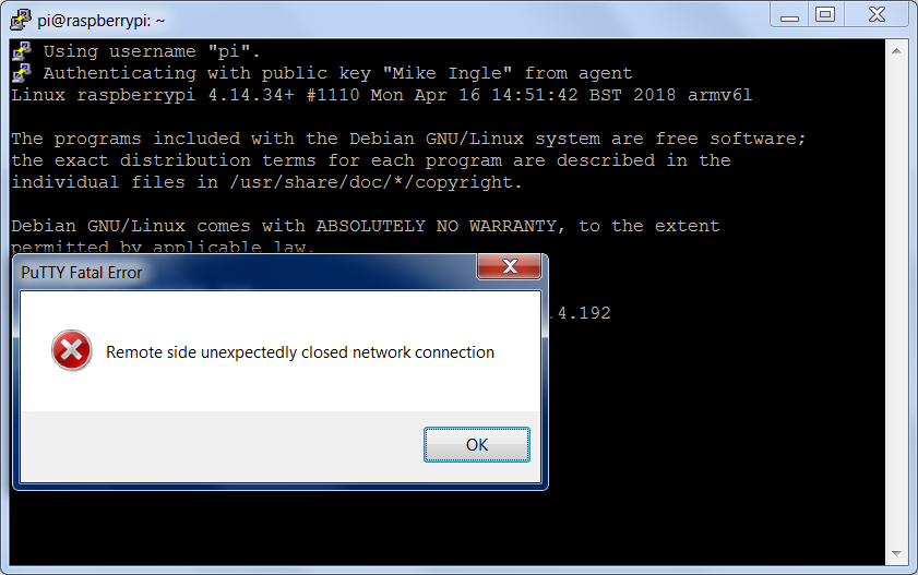
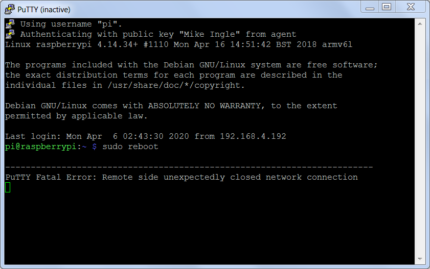
To make sure your remote device does not hang and stop responding to commands, you should have a keepalive script. The keepalive script can check the file date, last downlink time, and last uplink time in satcom_status.txt. Since your application should report in periodically, if those times don’t change within the expected interval, assume something is broken and reboot.

My project needed to send timestamps, GPS data, and other numeric fields. I wanted to keep a character string format rather than using binary, especially for the GPS decimal fields, so I used four-bit BCD with some delimiter characters. The bcdencode and bcddecode functions support the digits, space, decimal point, minus sign, and slash. An ASCII list of numbers can be converted to BCD, using half as many bytes over the air, and then converted back to ASCII at the server.

satcom_p.pl

identify_port.pl

They should have used CM: Deloitte

https://www.theguardian.com/business/2017/sep/25/deloitte-hit-by-cyber-attack-revealing-clients-secret-emails

The hacker compromised the firm’s global email server through an “administrator’s account” that, in theory, gave them privileged, unrestricted “access to all areas”.

It’s rather surprising just how bad the international elite’s security measures are. If you keep it in plaintext on a server, someone can steal it with a targeted attack. They should be using something that keeps no plaintext except on the endpoints, and use cheap dedicated laptops for the secure endpoints.

And encrypt the laptops.

Long-range passive RFID device

This device is an Alien Technology ALR-9650 RFID reader. It can read unpowered RFID tags from over 20 feet away. I am working on an RFID project at the moment, so I have one to play with.

Here is a collection of RFID tags. Most of these are badges or labels, one is a wire dipole, and there are a few plastic boxes. Each one contains a 96-bit serial number which can be remotely read.

Here are some close-ups of tags. Each tag has a tiny chip and an antenna. They do not have batteries.

This type of RFID is basically radar. The reader sends out a pulse of up to 4 watts in the 902-928 MHz range. The chip in the tag rectifies the received energy, using it to power some simple digital logic. The tag responds to the reader by varying the load on its antenna, so that the strength of the reflected signal toggles between high and low levels.

When there are many tags in range, there is a problem of them all talking at once. The reader handles this for you, using a complex algorithm to make a subset of the tags respond so it can identify each one.

This reader has Ethernet, a serial port, and some general purpose I/O. It can read on a trigger input, or trigger an output when it detects a tag. It requires either power-over-Ethernet or a proprietary 24-volt DC supply. There is an external antenna connector, which I have not tried. The reader runs Linux internally, and you can observe the boot sequence over the serial port.

The programming interface is a proprietary command line over telnet or serial. You can either manually ask for a list of tags, or set the reader to automatic polling mode. In automatic mode, the reader connects to a listening TCP port on your server and reports in when it detects tags. The reader can report the received signal strength of each tag, which increases as the tag gets closer to the reader. There are a lot of configuration options.

The reader’s built-in antenna is very directional, with a cone-shaped pattern from its front. Several of these tags would reliably read over 20 feet away indoors. Holding a tag close to your body reduces the range substantially. It was easy enough to write an RFID application using the Perl sockets interface.

Most of the tags can be written to. Within a foot or so, the reader can change the 96-bit identifier on a tag. Some tags also have a small amount of user memory, such as 64 bytes for the wire dipole tag. Some tags have passwords to restrict reading and writing of parts of the memory.

This passive radio technology was originally invented for surveillance bugs. The bug uses little or no power, and emits no signal of its own. When the spies want to listen, they aim a directional antenna at the bug and bounce a signal off it. The advantage is that the bug lasts a long time and is hard to detect. The downside is that the transceiver is very detectable, and will lead any bug-hunters right to the listening post.


Hack a receipt printer to print mini-banners

Print Shop was one of the most popular software programs of the 1980s. Among other things, it could print long banners with a dot-matrix printer. These banners were 8 ½ inches wide, and were too big for many purposes. This project prints three-inch wide banners using a credit card receipt printer and continuous roll paper. It can print one or two lines using any TrueType font.

The Verifone 250 is an old-fashioned dot-matrix receipt printer, used with a lot of credit card terminals. They are currently available cheaply on eBay, because the chip-card transition has forced the replacement of older credit card terminals. The printer uses three-inch roll paper. Ribbons are readily available on eBay as well.

Dot-matrix printers use a set of metal pins, driven by electromagnets, to strike a cloth ribbon and print dots on the paper. Most dot-matrix printers had nine pins in a vertical row on a print head that moved across the full width of the paper, printing a line of text in one pass.

The Verifone 250 is somewhat different in that it uses seven pins staggered across the width of the paper on a vibrating carriage. The carriage moves rapidly back and forth, printing one horizontal line of dots at a time, and then the paper moves forward one small step. It prints odd dots in one direction and even dots in the other, for a total of 420 dots across the three-inch paper width.

The horizontal resolution is 160 dots per inch, while the vertical resolution is only about 60 dots per inch. There are escape codes to print bitmapped graphics. The odd/even principle, and the large difference between horizontal and vertical resolution, have to be handled in software.

External power supply. Make sure you get one with your printer.

The printer uses RS-232 serial protocol with a proprietary cable. Make sure you get the external power supply and the proprietary serial cable along with the printer. The cable is intended to plug into a credit card terminal using a round connector. We will modify the cable to use a DB-9 female RS-232 connector. You will need a serial-to-USB adapter to connect the printer to most modern computers.

DB-9 connector wired to Verifone 250 cable

The serial port uses RTS-CTS hardware flow control at up to 9600 baud. There is a complication in that, unlike credit card machines, most PC serial ports have a hardware buffer. When the printer’s tiny buffer is full, it signals “STOP” to the PC. The PC serial port empties its buffer before it stops sending, and those extra characters get lost. This took a while to figure out. The software driver must send one character at a time, with pauses to keep the transmit speed slightly below the baud rate. That keeps the hardware buffer empty and prevents this problem.

I am using the ImageMagick software toolkit to generate bitmaps from text input and distort them to the printer’s aspect ratio. ImageMagick can use any TrueType font, which you can find in C:\Windows\Fonts on a Windows machine. The output from the ImageMagick commands is a one-bit uncompressed BMP file, which must have 420 pixels horizontally by any length.

My verbanner.c program, intended to run under Linux, converts the BMP file to the six-bit, alternating odd/even format expected by the printer, and sends it with the required hardware flow control and speed limits to print the banner.

I have some internal hardware documentation on the Verifone 250. It does not have a thermistor to shut it down if the print head overheats. This printer was designed to print a few lines of text at a time. If you print too much high-density graphics without a pause, you might burn out the coils. I do not know what the safe limit is, and do not have an infrared thermometer. I have printed some banners up to a meter long, and the printer was not overly hot, but you should be aware of this. If someone wants to measure the temperature rise over time, I will add cool-down pauses to the software.

When you get your printer, you can quickly test it by turning it off, holding down the paper feed button, and turning it on. It should print out a test pattern. The next step is to wire your cable. I just cut the credit card machine end off, stripped the wires, and soldered them to a DB-9 female connector. Here’s the pinout of the printer’s serial port:

This is the pinout looking at the printer’s port. If you are looking at the plug on the end of the cable, reverse left and right.

Here is the wiring to a PC serial port. I used the continuity beep mode on a meter to identify the wires. Your cable may have different wire colors than mine, so please check.

PRINTER   | PC DB9      MY WIRE [ DO NOT RELY     ]
 PORT     | FEMALE      COLOR   [ ON THESE COLORS ]
----------+-----------+-------
RTS PIN 3 | CTS PIN 8 | BLUE
CTS PIN 4 | RTS PIN 7 | WHITE
RXD PIN 5 | TXD PIN 3 | GREEN
TXD PIN 6 | RXD PIN 2 | YELLOW
GND PIN 7 | GND PIN 5 | RED

The printer has four DIP switches you need to set. They are on the right side of the mechanism. Remove the cover and ribbon. The settings shown (on, on, off, off) are for 9600 baud, 8 bit, no parity. These are the right settings for this project. There is a table of switch settings in the manual on page 7.

DIP switches properly set

These examples were run on Ubuntu 16.04. Plug in the serial-to-USB interface and the printer. Set up your machine:

sudo apt-get install imagemagick
wget https://www.confidantmail.org/download/verbanner.c
gcc -O -o verbanner verbanner.c
sudo chmod 777 /dev/ttyUSB0

You also need a TrueType font. In this case I am using arial.ttf from a Windows machine. Place that in the current directory.

Here are the commands for an example single-line banner:

convert -size x1500 -font arial.ttf -pointsize 200 +antialias -gravity center "label:Encrypt!" -rotate 90 -depth 1 out1.png
convert -depth 1 -crop 1240x+20 out1.png out2.png
convert -depth 1 -resize x37.5%%! -resize 420x out2.png out3.png
convert -compress none -flip out3.png out.bmp

The BMP file looks like this on the screen:

To print it:

./verbanner -b 9600 -o /dev/ttyUSB0 out.bmp

The printed banner:

This will look more solid when my new ribbons arrive from eBay.

Here are the commands for the two-line banner at the top of the article:

convert -size x1080 -font timesbd.ttf -pointsize 200 +antialias -gravity center "label:You have new\nConfidant Mail!" -rotate 90 -depth 1 out1.png
convert -depth 1 -crop 1040x+20 out1.png out2.png
convert -depth 1 -resize x37.5%%! -resize 420x out2.png out3.png
convert -compress none -flip out3.png out.bmp
./verbanner -b 9600 -o /dev/ttyUSB0 out.bmp

You could print graphics as well as text. Render the graphics as one-bit pure black and white, and use the resize and flip commands to scale them to match the printer’s aspect ratio. The Verifone 250 can also print in red. The verbanner.c program would have to be altered to support this.

Here is the verbanner.c program.

Here is the Verifone 250 printer manual.

Defective phone charger – 44 volts and a big blue flash

Every few months there are stories of mobile phones and chargers catching fire, but it’s not often that a defective charger blows up while connected to a voltmeter.

This was a generic 2-amp charger that I received with a used phone at an independent cellphone shop. I had it for over a year. Recently, I used it to charge an old Galaxy S3 which I was using as a music player. After a while, I found the phone hot to the touch and not charging. I tried another charger, and no luck – the phone would not charge.

Fortunately it was an old inactive phone, not the one I use every day. But did the phone just fail, or did the charger destroy it? Today I decided to find out. I connected the charger’s output to a Fluke voltmeter set on DC volts, watched the display, and plugged it in.

The meter takes about half a second to settle down. It showed 44 volts for less than a second. Before I could unplug the charger, there was a blue flash and a pop from inside it. The charger had lost regulation, destroyed my phone, and could have started a fire.

Burst capacitor on input side

How is that even possible? How can a device designed to put out 5 volts go all the way up to 44 volts? Shouldn’t the transformer step-down ratio be too high to allow that?

As it turns out, modern cell phone chargers do not use a regular transformer, or even a “forward converter” switching power supply. Since they are supposed to work efficiently from 100 to 240 volts input, they use something called a “flyback converter” which does not have a fixed input to output ratio. Unlike an old-fashioned transformer, it can “go wild.”

Swelled 10-volt rated output capacitor

The way this works is, a transistor turns on and generates a magnetic field in the primary of the transformer. When the control IC turns off the transistor, the magnetic field collapses and dumps its energy, through the secondary winding and a diode, into the output capacitor. Operating on 240 volts, the controller just turns off the transistor sooner than on 120 volts.

Various fried surface mount parts. Board is divided into input and output sides.

If the regulation fails, the controller will leave the transistor on too long during each cycle. The output capacitor will just keep charging up, until either the load draws enough current to limit the voltage, or a component fails. This “flyback” design is inherently unsafe unless it has an over-voltage shutdown circuit – which this cheap no-name charger did not have.

With a phone attached to the charger, the phone’s input circuit failed, got hot, and could have caught fire. Without a load, the voltage kept rising until several components in the charger blew up.

Poof! Tiny surface-mount parts contain a lot of magic smoke.

Classic audio equipment and corporate stupidity

If you were a music executive in the early 1990s, this was your worst nightmare:

The music industry at that time was not afraid of the Internet, or the PC, or Apple. They were afraid of machines like these, especially in pairs. These devices terrified the industry into a series of big mistakes. What is so scary about some old-school audio equipment?

A little background: Hi-fi digital recording was invented in the late 1970s, and the equipment had a six-figure price tag. You needed a broadcast-quality videotape machine and a big box called a PCM adapter. The first PCM adapters were used to master LP records which were advertised as “digital” even though they weren’t. Philips and Sony introduced the CD in the early 80s, and many people at first thought the design was expensive overkill. The CD preserved the full sound quality of the professional PCM adapter.

The music industry was a little nervous about the CD from the beginning, because one CD could be used to record an unlimited number of cassettes, and the “pirate” tapes often sounded better than prerecorded tapes. The industry got over their fears when CDs started making them a fortune. CDs were cheap to mass-produce, cheap to transport, didn’t break, and sold for more than records or tapes. Until the mid-1990s, even recording studios could not make a one-off CD.

The Japanese audio industry built CD changers and tape decks optimized for automatically making mix tapes. The fancy ones could even pause the tape while the CD changer cued up the next disc. The music industry grumbled that “Home taping is killing music!” and lobbied for a tax on blank cassettes.

Sony introduced a semi-affordable PCM adapter called the PCM-F1 that plugged into a Betamax VCR. It didn’t sound quite as good as a CD player and the tapes were not reliably interchangeable between VCRs, among other problems. The PCM-F1 was more popular with musicians than with audiophiles.

Then in 1987, Sony announced the Digital Audio Tape recorder, and the music industry instantly freaked out. The DAT recorder is a high-quality cassette deck, with the same audio specifications as a CD player. The cassette is smaller than a regular audio cassette, and holds up to two hours of music. The machine uses a camcorder-style mechanism with the tape wrapped around a spinning drum. Each tape holds over a gigabyte, which was a huge amount of data at the time.

Unlike the PCM-F1, DAT recorders do have digital I/O, and can make a digital copy of a CD that theoretically sounds identical to the original. With two machines, you could also make an exact copy of the copy. The music industry feared an epidemic of chain piracy that would kill the CD business. They filed lawsuits and lobbied Congress, using the analogy of Pearl Harbor: the evil Japanese electronics industry had launched a surprise attack to torpedo the poor helpless American music industry.

For several years, DAT recorders were hard to come by. There were classified ads in the back of audio magazines: “We Have DAT Recorders” followed by a phone number. The music industry was demanding a copy protection system, and here is where they made the mistake that led to MP3s and the iPod.

The compromise worked out in 1992 was called Serial Copy Management System (SCMS). The law divided DAT machines into consumer and professional machines. With consumer machines, you could make a digital copy of a CD, but you could not digitally copy the copy. You could always make an analog copy, and a first generation analog copy has very little degradation. Pro machines were not restricted. The law did not clearly specify what a machine had to have to be declared professional, and anyone who wanted to spend the money could buy a pro machine.

The computer industry objected to this deal. Computers could already record and play digital audio. A computer that could not copy files wasn’t much use. The music industry did not want to fight with the PC industry, so they agreed to a complete exemption for “computer hard drives.” At the time there was no affordable hard drive that could hold even a single CD. Fortunately for tech, lawyers don’t think in terms of exponential growth.

Were the industry’s fears reasonable? Not really. First of all, DAT machines started close to $1000 and went up from there. The tapes were almost as expensive as CDs. You needed two machines to copy tapes, and copying an hour’s worth of music took an hour. The tape has no title or artist catalog, so keeping track of a large collection is a lot of manual work. Just about the only people who used DAT as a copying medium were concert tapers, who were fanatics and would invest huge amounts of time and effort in getting rare recordings. It would be very hard to save any money by pirating CDs on DAT tapes.

By the late 1990s, the PC world had changed. Hard drives held over a gigabyte, 16-bit sound cards were common, and so were CD-ROM drives. The music industry had not made any effort to restrict CD-ROM drives, so most of them could rip audio CDs. Once the Fraunhofer MP3 codec and Winamp player came along, people started sharing music using FTP sites and badly formatted web pages. I learned about MP3 from an article about the music industry trying to shut down such sites.

At first, the PC was the only device that could play MP3s directly. Diamond Multimedia came out with the first portable flash-memory MP3 player, the Diamond Rio. It held less than an hour of music. The music industry sued Diamond, claiming this was an illegal device since it did not have SCMS – it would play a second-generation copy. The court decided that the Rio was not actually a recording device; it had no audio input, and it couldn’t copy anything by itself. The copying took place on a hard drive, and those were specifically exempt. Shortly thereafter, Apple introduced the iPod, and Napster came along.

The music industry did not understand exponential growth. They bought a law to restrict DAT recorders and thought the problem was solved, paying no attention to progress in PCs and hard drives. The music industry could probably have slowed things down by lobbying to make CD-ROM drives unable to rip audio CDs. However, computer-based digital music was going to happen regardless, and the industry should have planned for it.

As an example of music industry thinking, in 1999 Sony introduced a Minidisc recorder with a digital link to a satellite TV receiver, which would let you buy music from their proprietary music store. MP3s and the Internet were already around at the time, and Sony was still plugging cables between two proprietary boxes. Sony was especially bad in this regard; their technically excellent Minidisc equipment had restrictions even beyond what the law requires. I’m going to write an article about Minidisc soon.

What’s it like using a DAT recorder? They are somewhere between a tape deck and a CD player. Analog recording is much like a regular tape deck, except you have to watch the levels carefully. The machine will indicate OVER and will sound nasty on playback. The DAT format has precise time code, and you can set “start IDs” and seek to the next or previous ID. If you copy digitally from a CD, the start IDs get set automatically. I can plug my Zinwell media player into the DAT using a TOSLINK optical cable and record from FLAC files.

After recording, the machine can number the start IDs, giving you track numbers like a CD. You can even play tracks in programmed order, with much whirring and clicking between songs. During playback, the DAT transport is nearly silent. Audible fast forward and rewind produce a choppy series of snippets. Seeking to a start ID is very fast, and the machine stops abruptly and then backs up slightly before it starts playing.

Of the two machines above, the Sony on the bottom is a consumer machine and the Panasonic is a pro machine. The Sony has regular RCA jacks for analog I/O, and will record from a radio or phono amp. In addition to CD-quality mode, it has a four-hour mode that is roughly FM radio quality.

The Panasonic has only balanced XLR analog inputs and outputs, so I’d need an adapter to do analog recording from a consumer source. The headphone jack works fine as an analog output, and both machines will take digital SPDIF or TOSLINK input.

The Panasonic SV-4100 is a radio station machine, often used to play commercials, so it has a neat quick-start mode. It can cue up to a start ID or to a manually entered time, loading a few seconds of audio into a 1 MByte RAM buffer. You can turn the dial forward and back to audibly choose an exact spot within the RAM. When you press Play, the sound starts instantly, and the tape transport catches up and syncs with the memory buffer. It may be obsolete but it’s quite a piece of engineering.

If you buy a DAT recorder, expect to have to fix it, and assume any machine that you can’t test is broken. The mechanisms are complex and some are more reliable than others. The Sony DTC-60ES cost $40 on Craigslist, but I had to rebuild the transport with parts from a dead donor machine. The Panny was also $40 at a pawn shop, and it just required a careful cleaning. The manual says the head drum lasts 1000 hours, and mine has 600 hours on the meter. DAT recorders are fun to play with and still sound great. However, they don’t make the parts any more, so you cannot use it every day.

The DAT transports require calibration to be compatible with each other. The data is recorded as a series of diagonal stripes on the tape, and the angle has to be just right. You’re supposed to use a calibration tape. In my case I calibrated the Sony to match the Panasonic, and they will now play each others’ tapes. Calibration involves connecting an oscilloscope to the head switch output and adjusting a pair of tape guides to get a flat waveform. The service manuals are generally available online, and explain how to do this.

Portable DAT recorders, the size of a larger Walkman, do exist. They are expensive, delicate, and required periodic service which is no longer readily available. They were mostly used by movie and TV sound technicians to record dialogue. They sounded good, and ran at a very precise speed making it easy to sync sound with picture. The DAT recorder has been largely replaced by digital card recorders like those made by Tascam and Zoom. The card recorders provide the same sound quality with no mechanical complexity.

Here’s a bit of trivia that might win you a bet: DAT recorders are only stereo devices; they cannot play back 5.1 surround sound. Right? Well, there is a standard for recording a DTS bitstream on an audio CD. Queen and Pink Floyd did some impressive surround mixes. These CDs will produce static in a CD player without a decoder, because they have the DTS bitstream where the PCM sound belongs. If you make a digital copy of such a CD on a DAT machine, it will play back as static. However, if you plug the digital output from the DAT machine into a home theater receiver, you will get surround sound.

The DTS audio may drop out now and then (the Sony works better than the Panny here) because of the DAT error concealment. That is the final irony of the music industry’s crusade against DAT: it’s not really lossless! There is quite a bit of error concealment, and multiple generations of DAT clones will suffer generation loss. This is true of multi-generation CD clones too; audio CDs usually don’t rip the same twice. The DDS computer tape format, derived from DAT, adds a second layer of error correction, and so does CD-ROM.

Large-attachment email is a powerful tool against video censorship

At the moment there is a big fuss about Internet video censorship, with several of the large platforms trying to kick certain opinions off the Internet. This should concern you even if you don’t like those particular opinions, because once censorship becomes common, anyone unpopular can be targeted.

Nobody worries too much about text censorship, because text can be easily saved to a file, forwarded in email, pasted into chat, and copied into discussion forums. Text is easy to copy and hard to censor.

Video is a powerful method of communication, but is currently easy to censor, because video platforms are centralized. People forward links, and the links tend to go away before recipients get to watch them. You can use ClipGrab to download video from the major platforms, but the resulting files are too large for regular email. Videos hosted directly on websites are likely to crash the site if the link goes viral, so most forums and blogs don’t let you upload large videos.

To prevent censorship, we need a way to send someone a video. Not just send a link, but actually send the video content to the person so that it cannot go away. Until recently there was no easy way to send a file over a few megabytes.

BitTorrent is good for few-to-many sharing of TV shows and movies, where there is an organized group seeding the videos, but it’s not a practical tool for person-to-person sharing. The sender would have to leave his computer running with a port open until the recipient finished downloading the video.

Many instant messaging services can send file attachments, but they are not reliable for large files, they lack privacy, and both users must be online for the duration of the transfer. Interrupted transfers cannot be resumed.

Confidant Mail is the solution to this problem. When you have your friends as CM contacts, and you want to show them a video, you just attach it and hit send. The recipient gets the file and can forward it freely. Third parties cannot censor specific videos, because they can’t see what you are sending. Users can move their accounts between CM servers without losing their identity or informing their contacts.

Confidant Mail is already being used to bypass video censorship and national firewalls. It makes videos as easy to share and forward as text and images. If you are worried about the large platforms being able to ban whatever they don’t like, install Confidant Mail and get your friends on it. You will no longer have to worry about other people deciding what you can see and share.